Reviving a retired scooter from a popular ridesharing service.
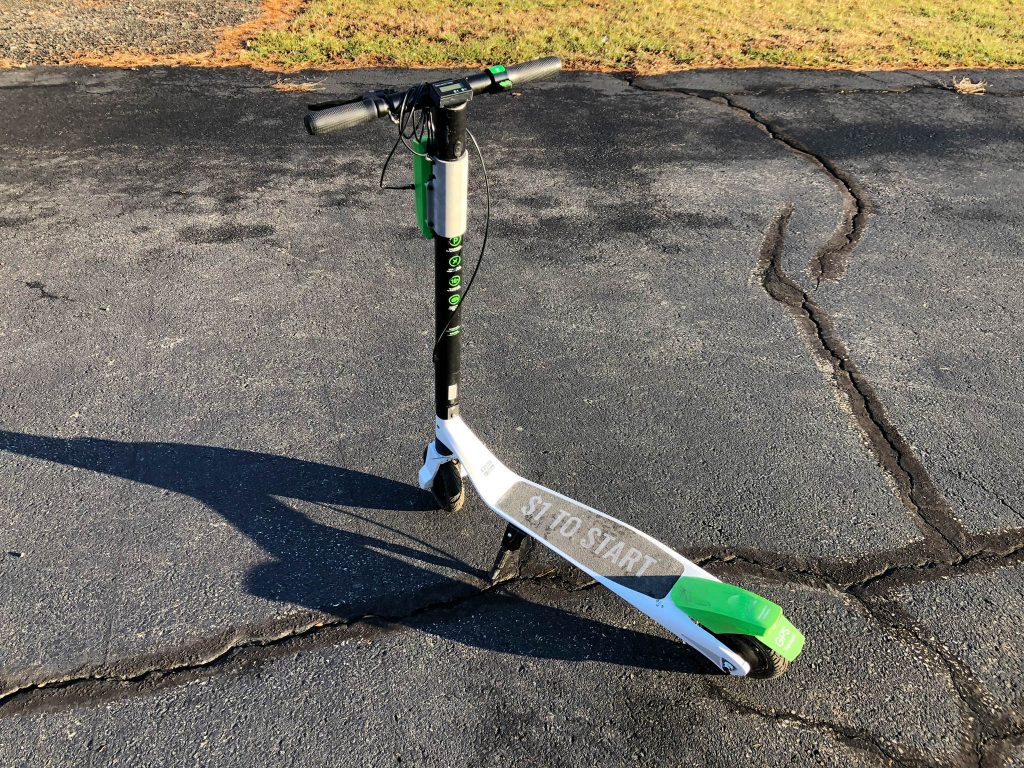
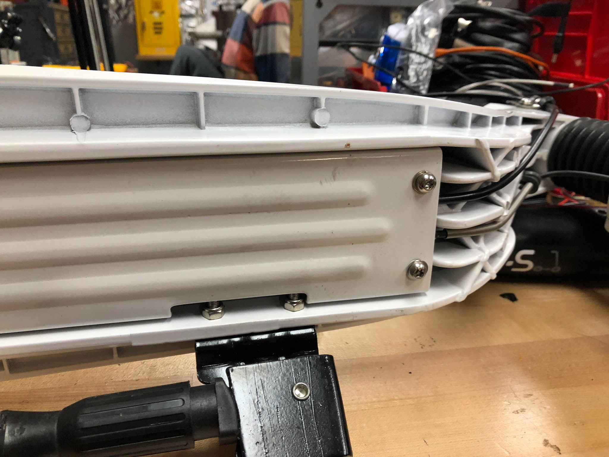
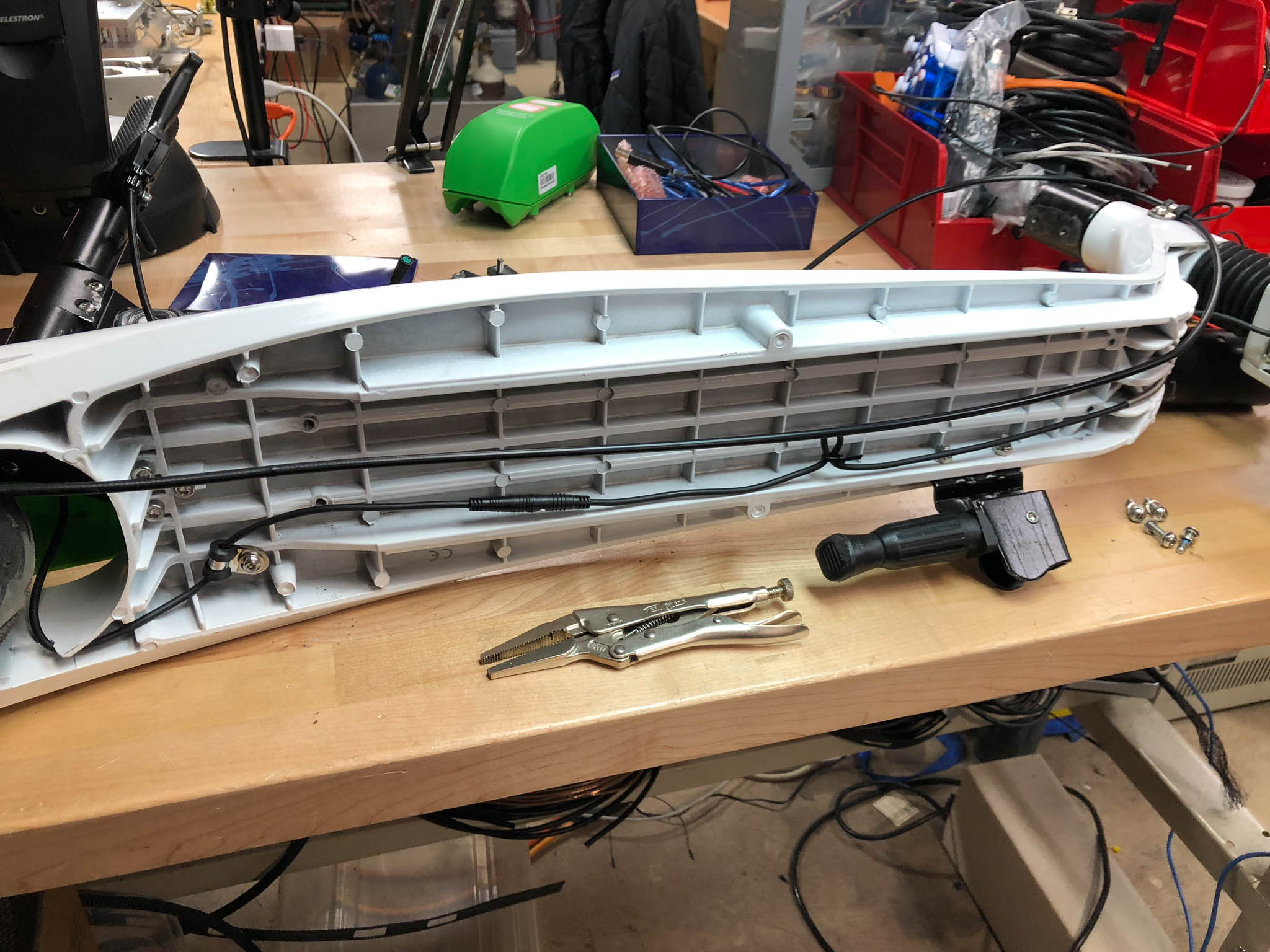
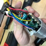
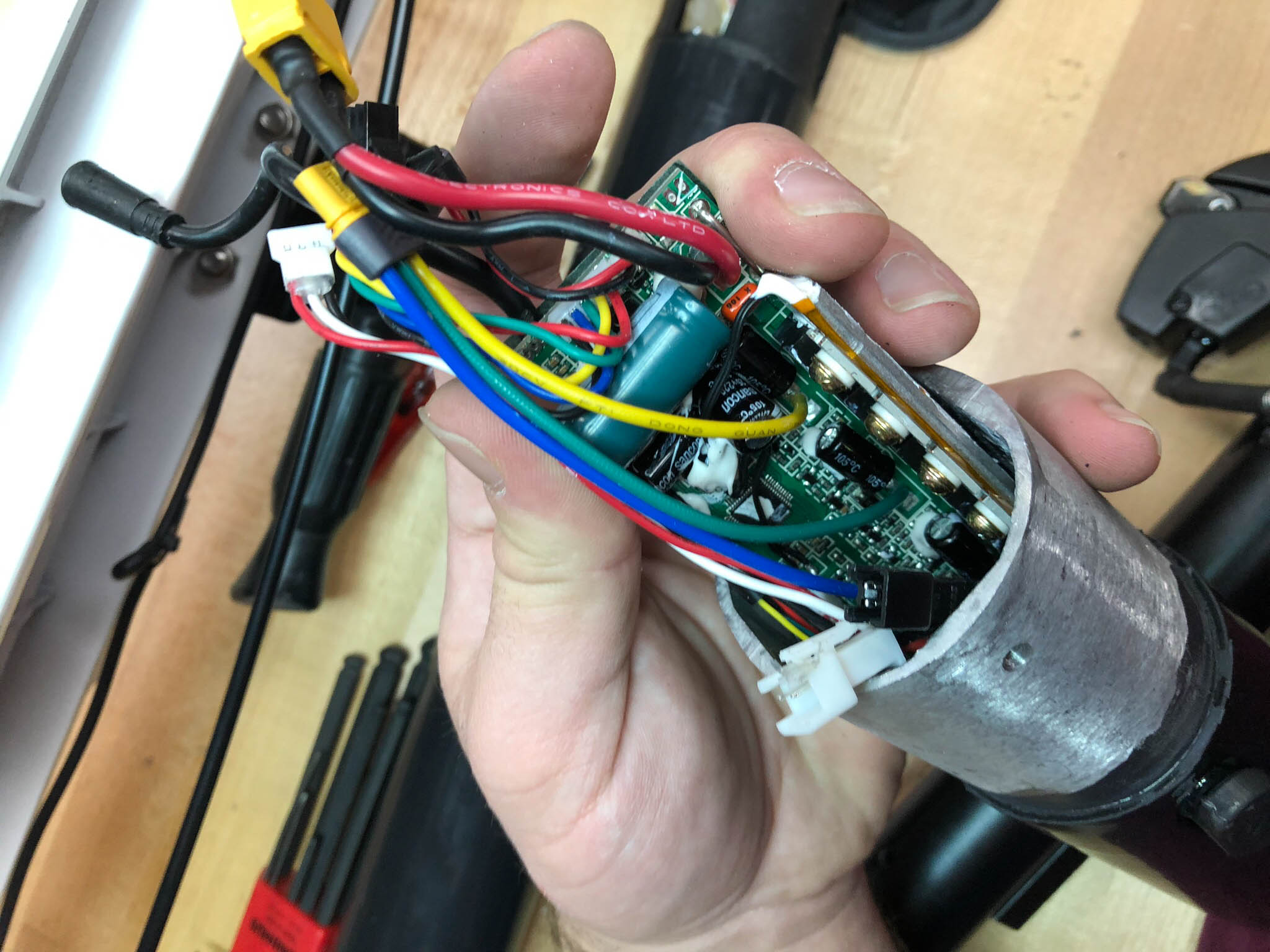
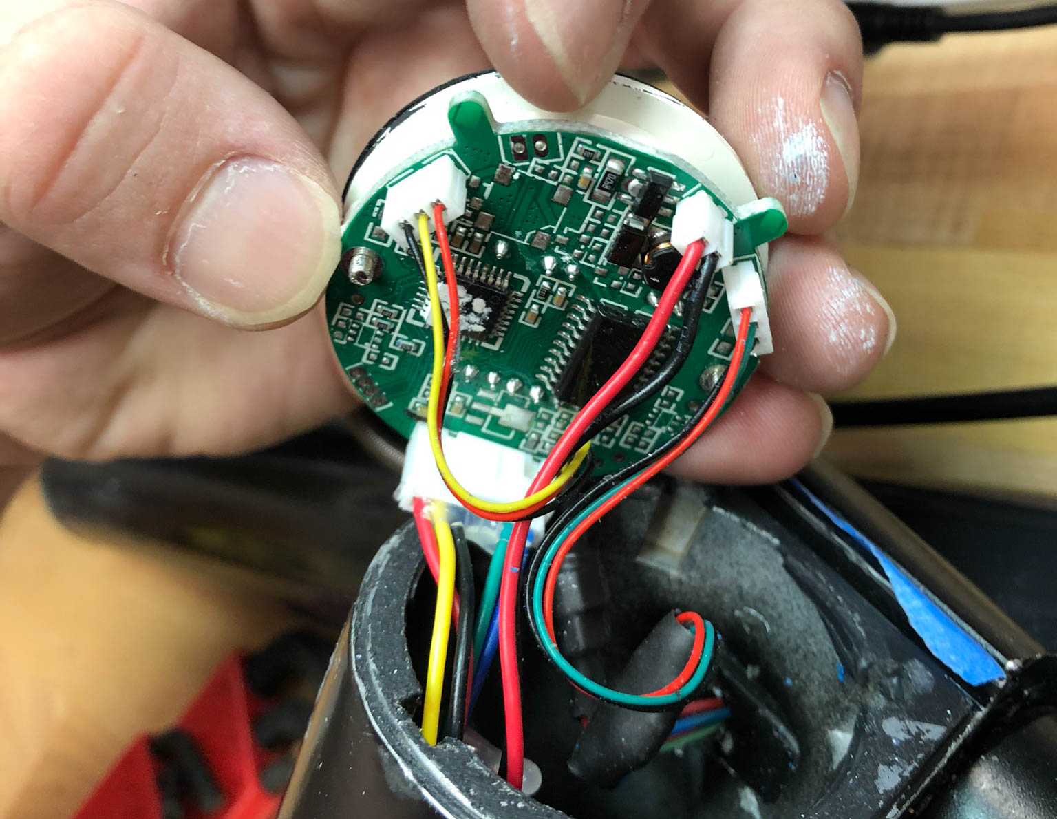
Sam and I were fortunate enough to (legally) come across a retired electric scooter and decided getting it going again would be a fun project- if, for no other reason, because this predominately West-Coast fad would look so out of place in NJ and Pittsburgh. We started with a teardown (gallery below), during which we learned that the scooter is powered by a 36V, 12.8Ah, 460.8Wh 10-cell LiPo battery which takes up the majority of the steering column. Above the battery is where the column mates to the handlebar assembly. A board which houses the ESC and charging circuitry lives in that region. The board has a STM32 microcontroller which receives UART commands from the on-board Android “cell phone” (housed in the green box on the front) to activate the ESC. The speedometer is above the ESC/charger, and is a screen which displays speed, battery level, connectivity, etc. It is controlled by a small board below it. The throttle is a hall effect sensor and provides an analog voltage output, which is read by the ESC. The motor is housed within the front wheel and is rated at 250W. There is also an encoder which reports wheel revolutions to the control board. Before we get to the fun part (how we made it move again), here’s the teardown gallery:
-
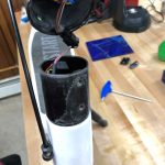
- Separating the steering column from the base
-
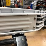
- The bottom plate is held on by four screws
-
- Not much going on below the bottom plate
-
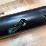
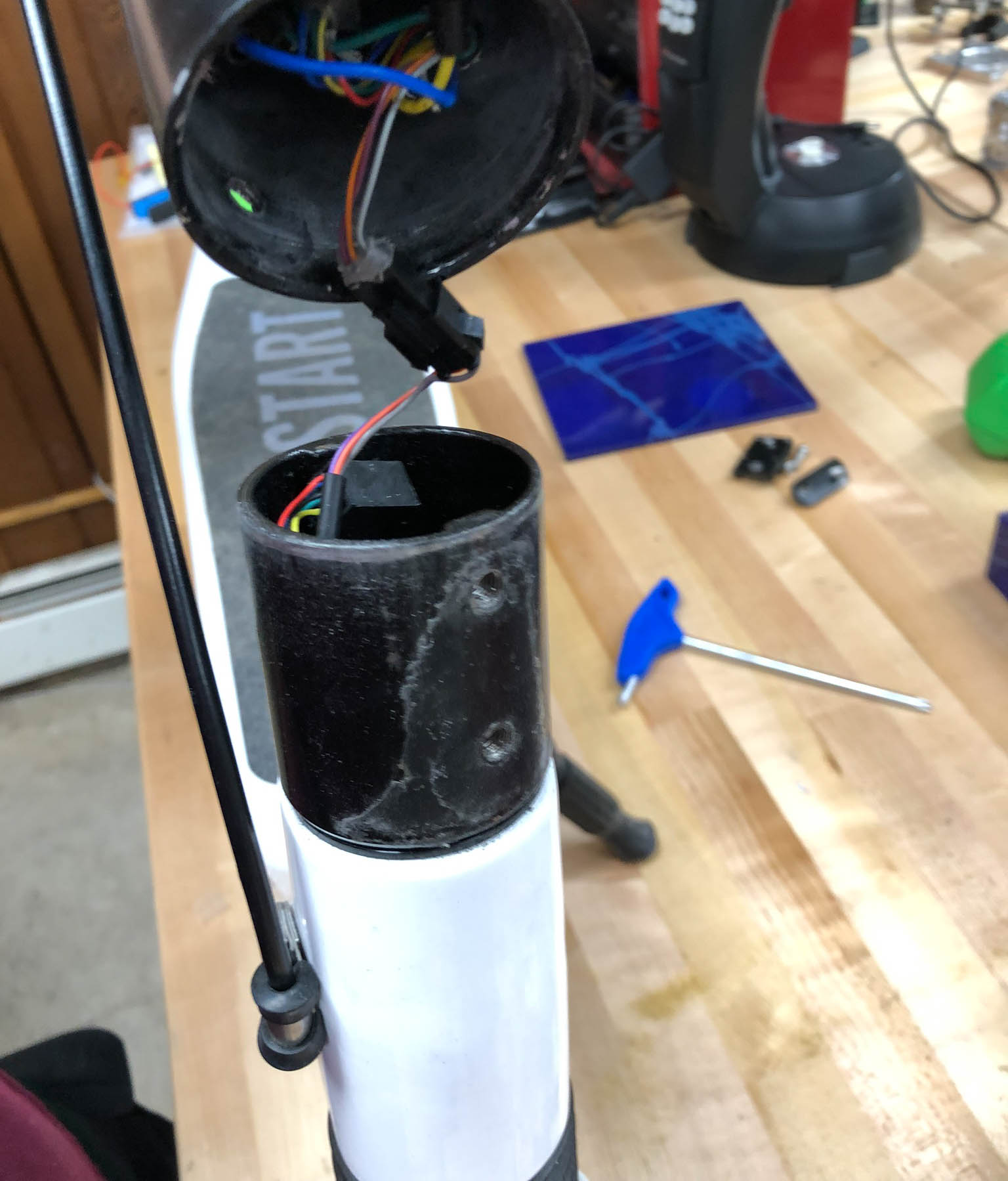
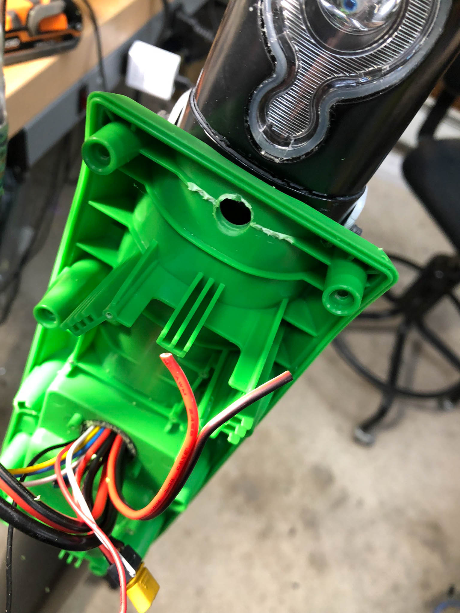
- Where the green box mounts- this data cable connects the Android board to the ESC

-
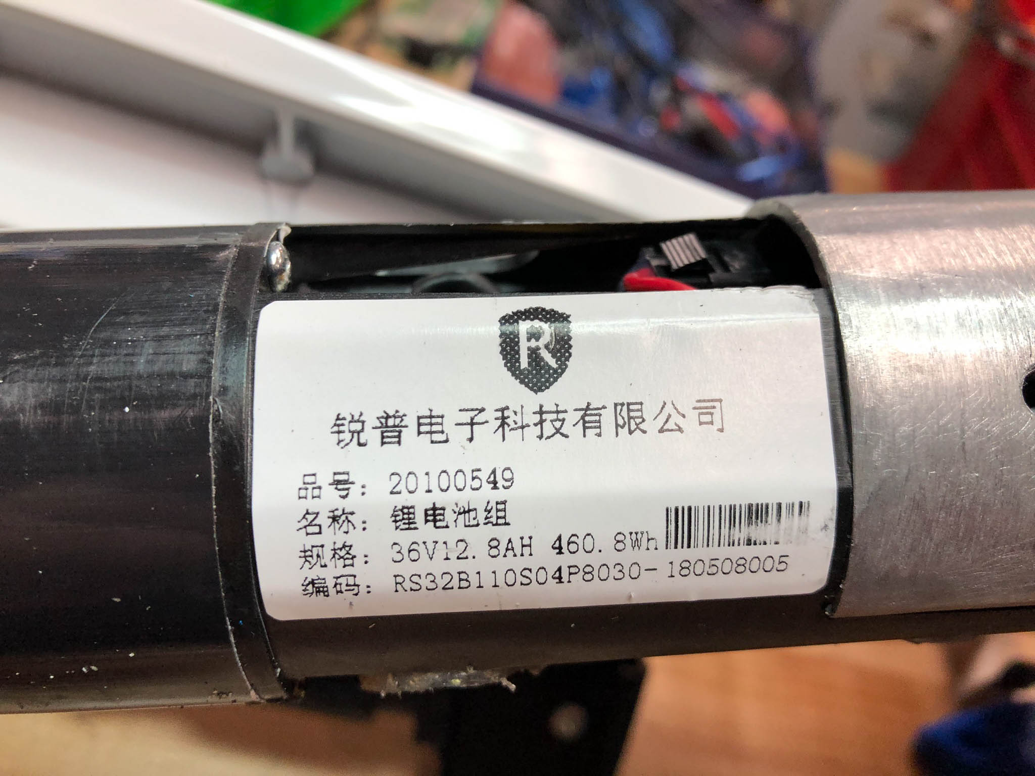
- Battery specs
-
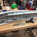
- Removing the handlebar assembly from the steering column
-
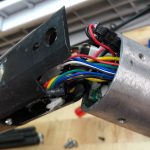
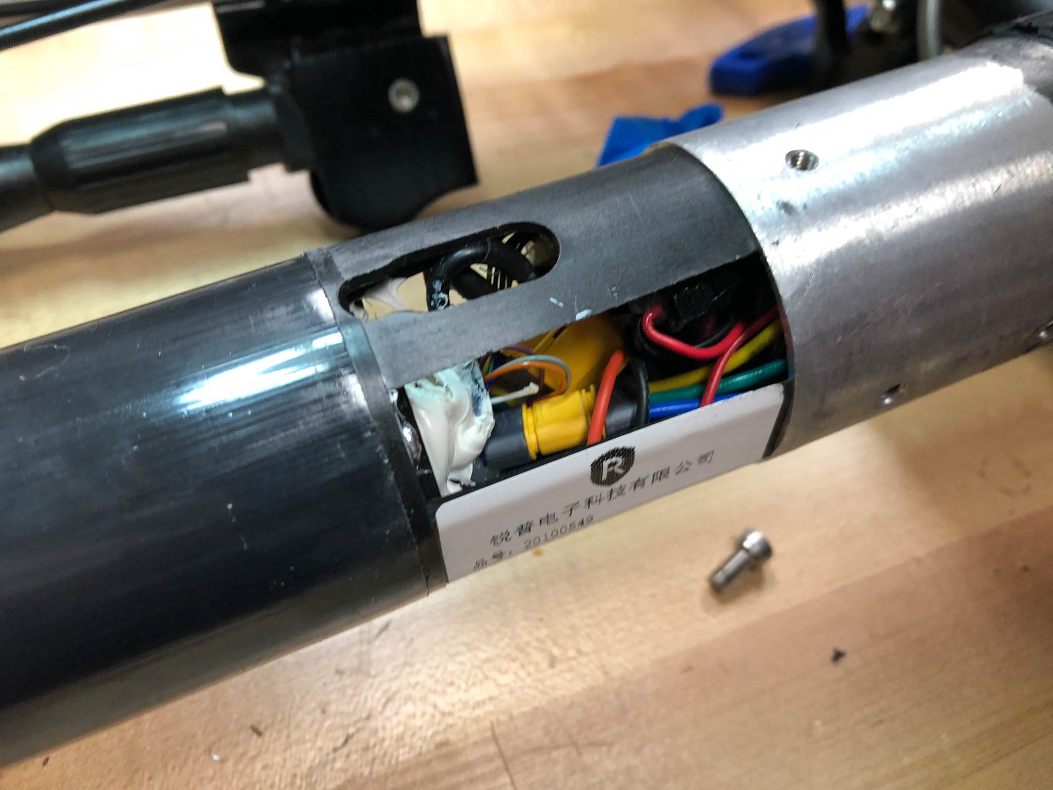
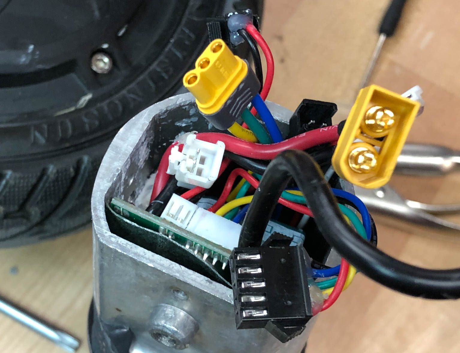
- So many wires
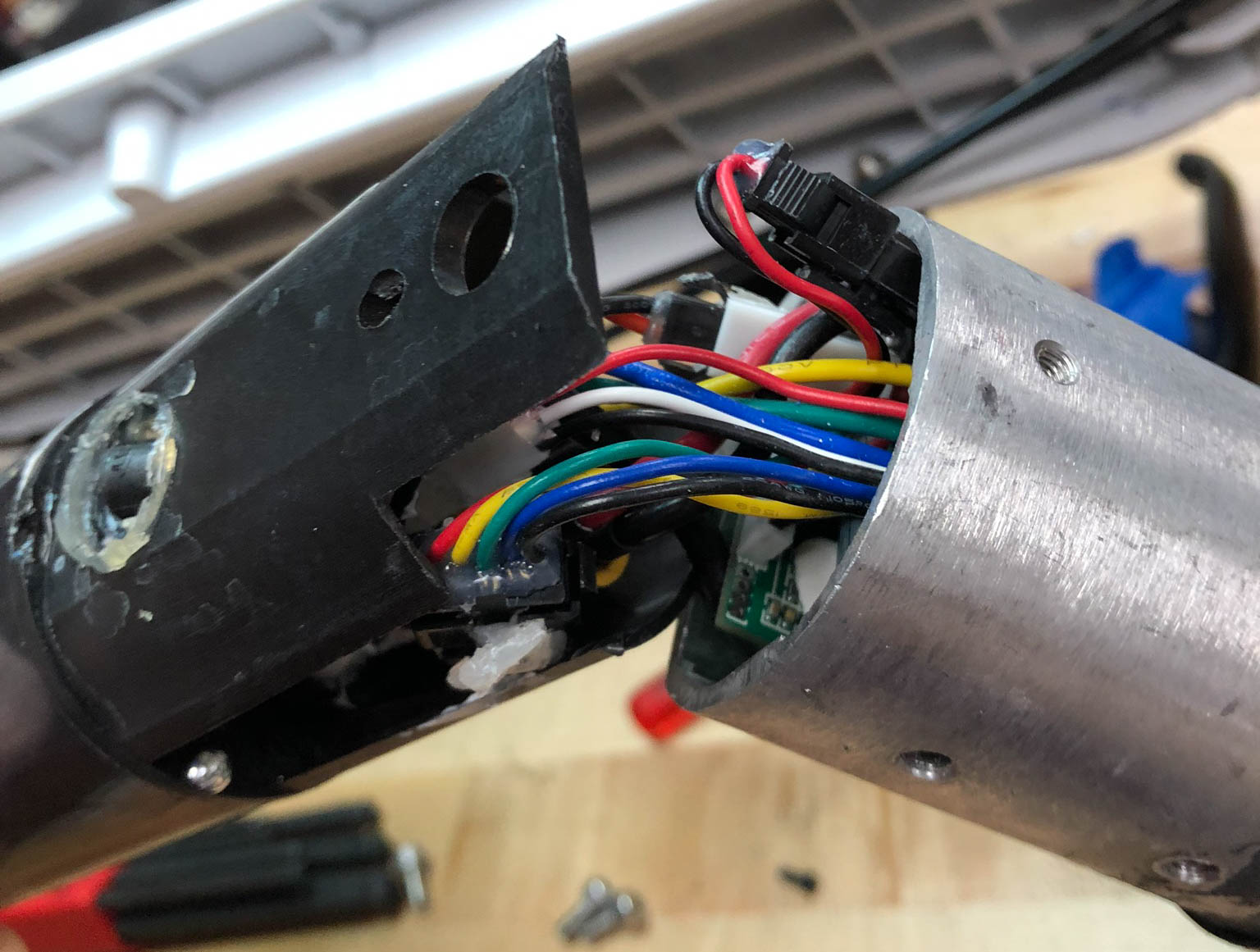
-
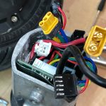
- More wires
-
- Removing the ESC from the handlebar assembly
-
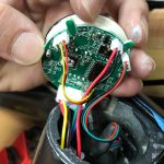
- Removing the spedometer from the handlebar assembly
-
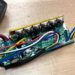
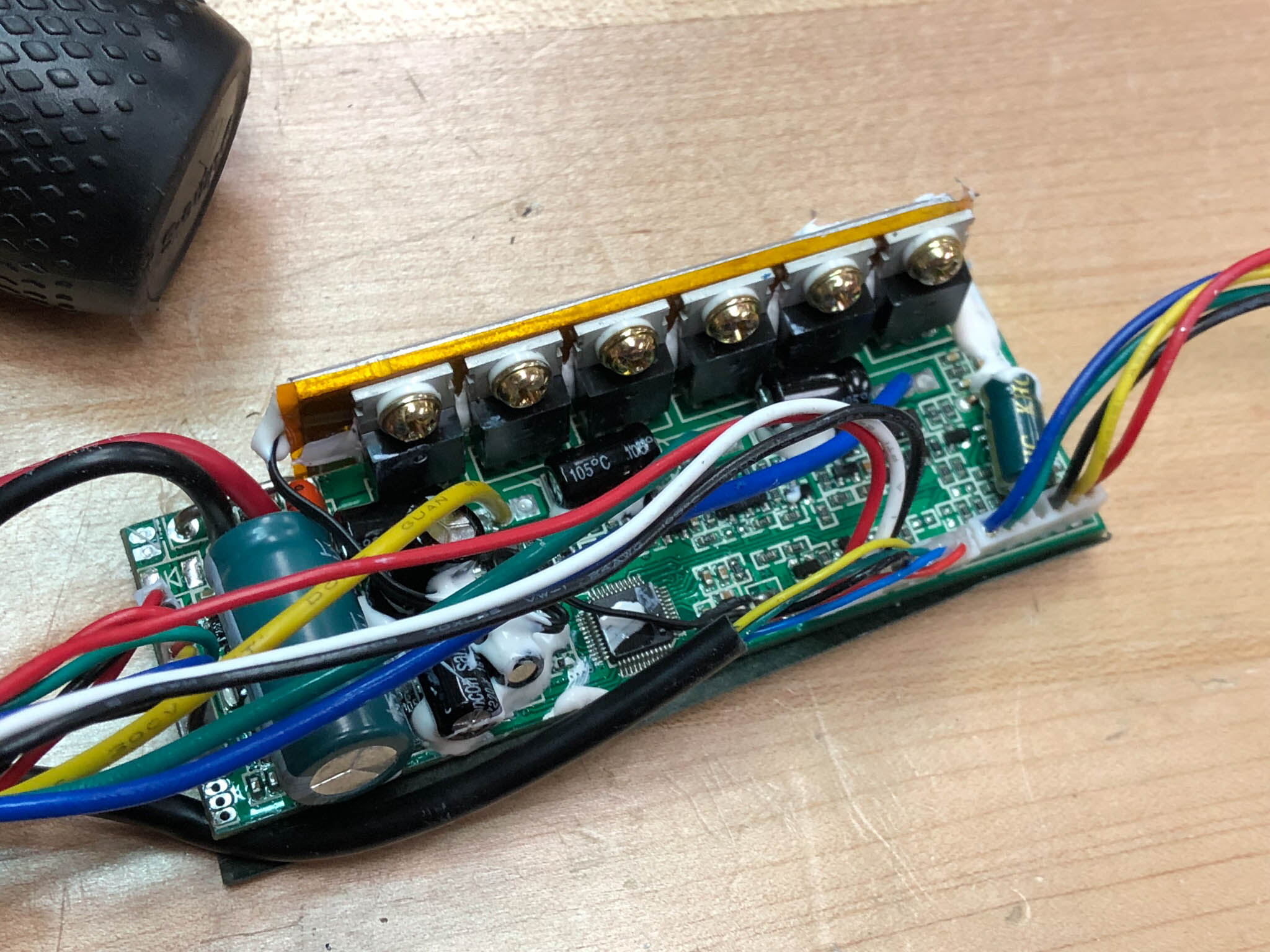
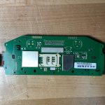
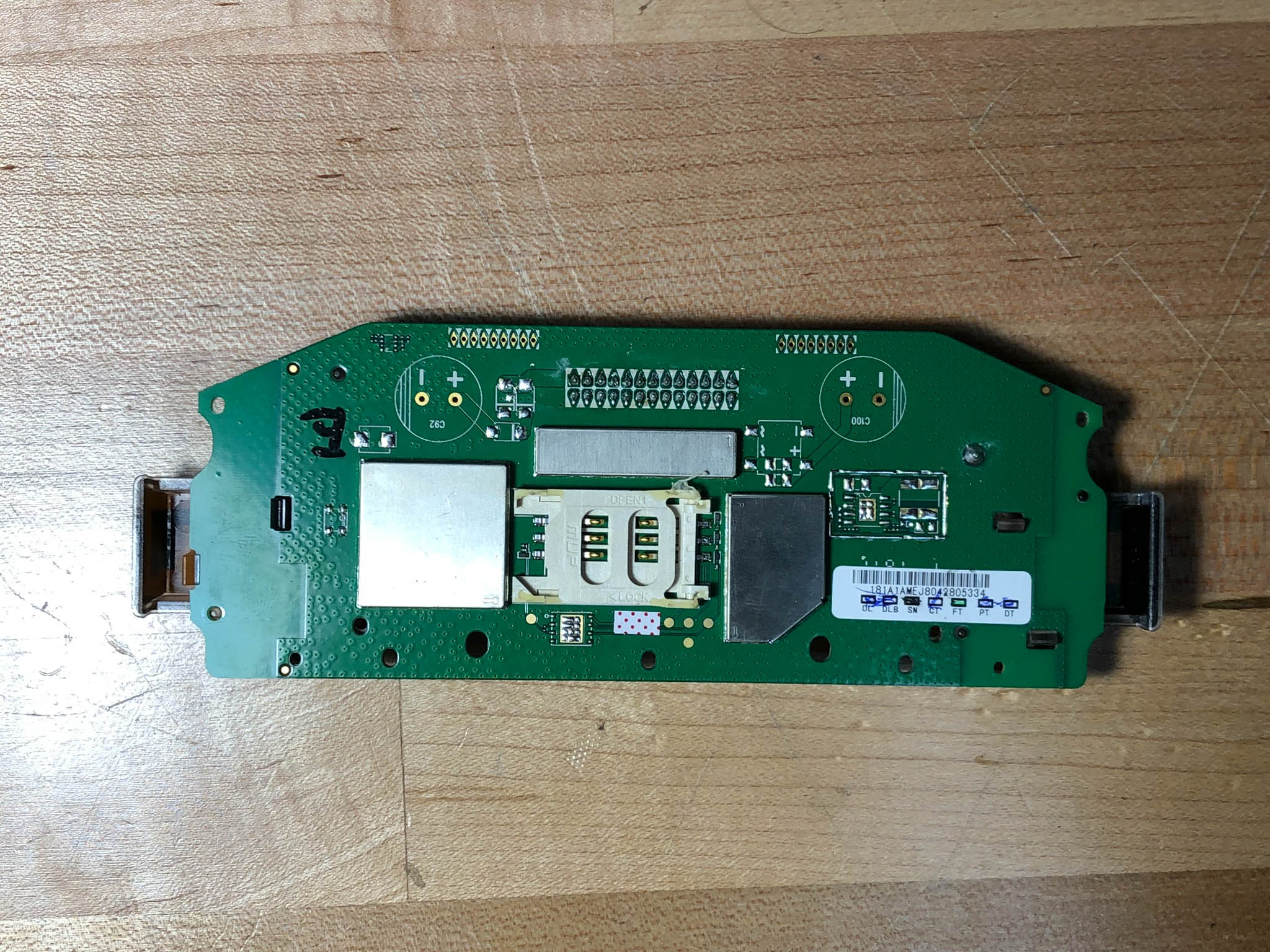
- The ESC/charging circuitry
-
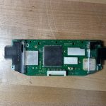
- Top of the Android “phone”
-
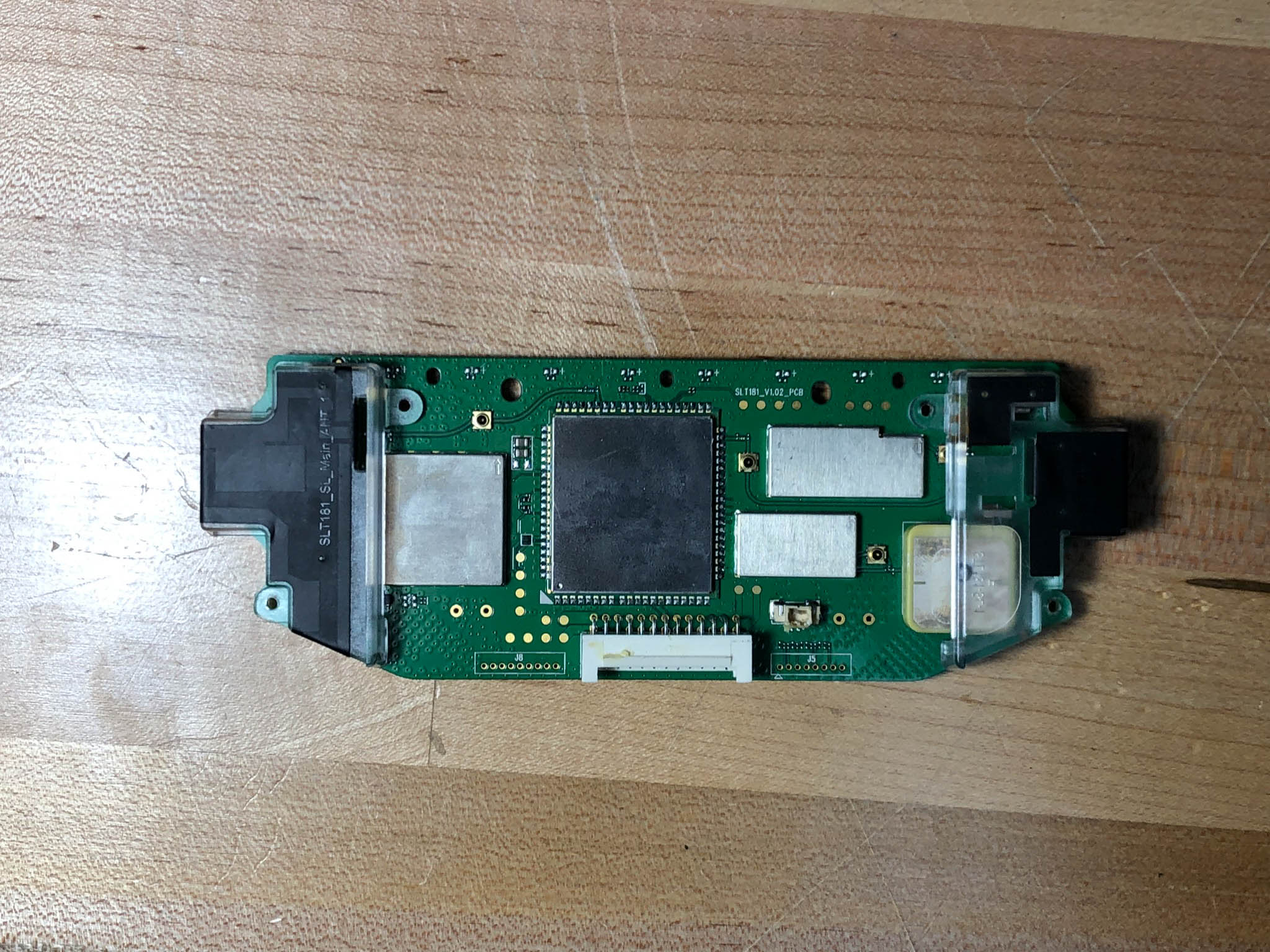
- Bottom of the Android “phone”
-
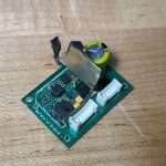
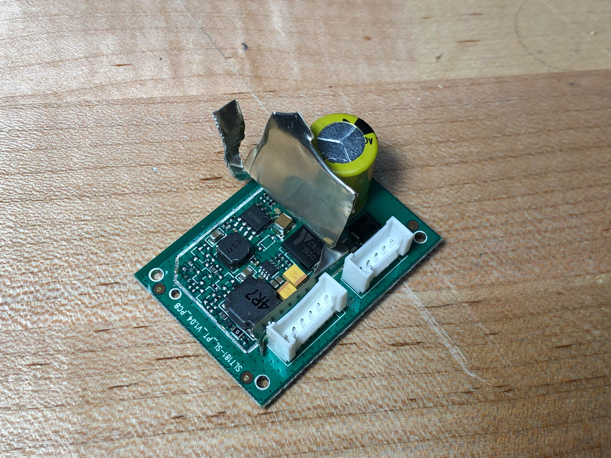
- Power supply? I forget what Sam said but he apparently didn’t like it much
To make this thing run again, there were a few options. The most complicated would be to attack the Android phone on-board and attempt to get it to send an activation signal to the ESC (normally, the scooter is unlocked when a user selects it in a mobile app). That seemed both hard and unnecessary, so we opted not to. The second option was to try to spoof the UART commands being sent to the ESC, to try to unlock it without using the Android board. If we had a live scooter that we could use, this wouldn’t be too difficult, as we could sniff the communications between the two boards and (hopefully) figure out the command set. Ultimately, we opted to rip out anything that had to be programmed and replace it with new hardware. This meant that the Android board, the ESC, and the charging circuitry went away.
After extending and re-routing a bunch of wires (and ignoring some, if we didn’t know what they were for), we were ready to install our new hardware. The ESC was replaced with the HGLRC-FLIPSKY FSESC 4.12 , which is based on the open-source VESC project. We decided to handle charging externally, using a generic 10s LiPo charger. We replaced the screen with a small XCSOURCE battery monitor– it doesn’t display speed, but battery level is what we really care about. We 3D printed an adapter to mount it where the old spedometer was. Finally, we replaced the android cell phone with a toggle switch. The ESC, toggle switch, and most of the wires were stuffed into the green box with the help of some heat shrink tubing and foul language, and that was the end of it. After some tuning and parameter-guessing with the VESC software, we were ready to ride! Here’s the assembly gallery:
-
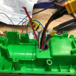
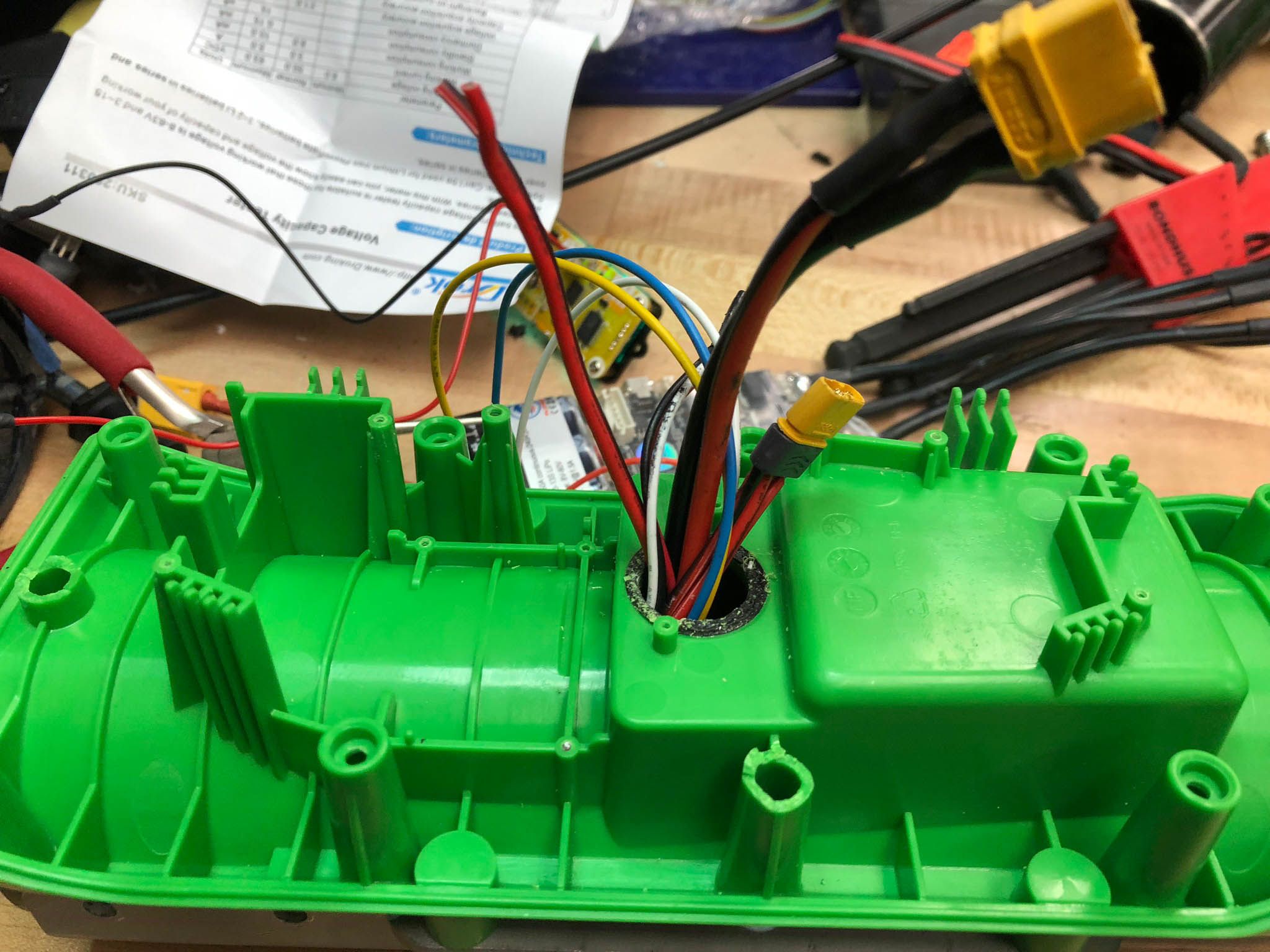
- Getting all the wires into this box took way too long. I don’t even know what they all do (and this is only half of them)
-
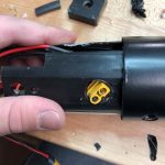
- Running a wires from the battery into the green box

-
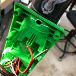
- Wire-filled box mounted on the steering column
-
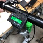
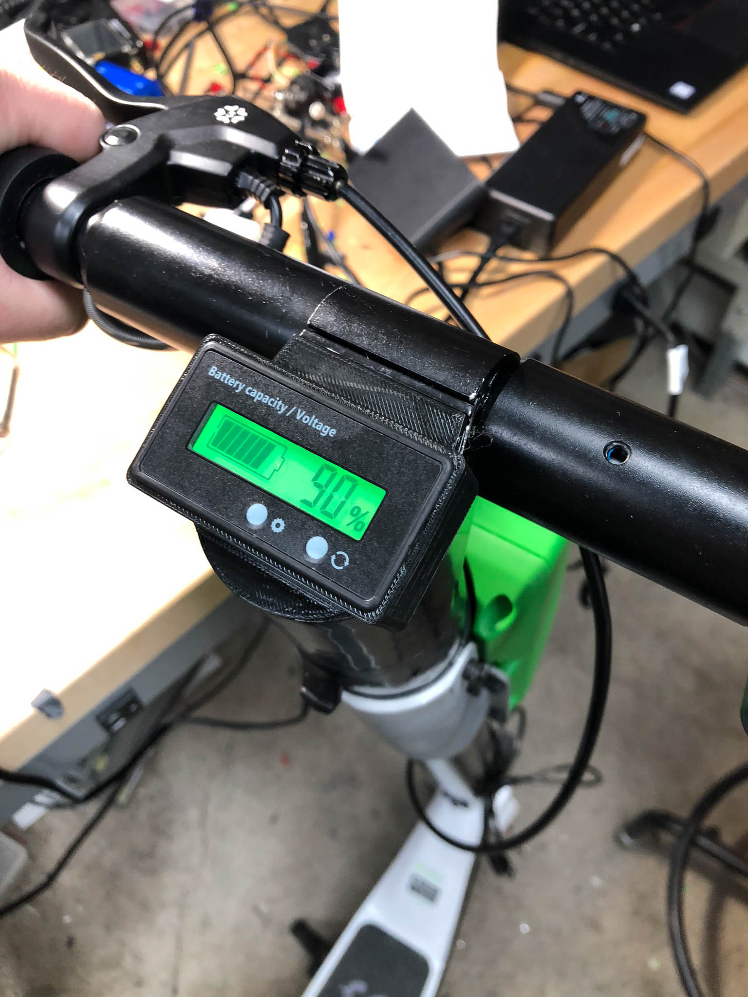
- The new battery display and it’s 3D-printed mount
-

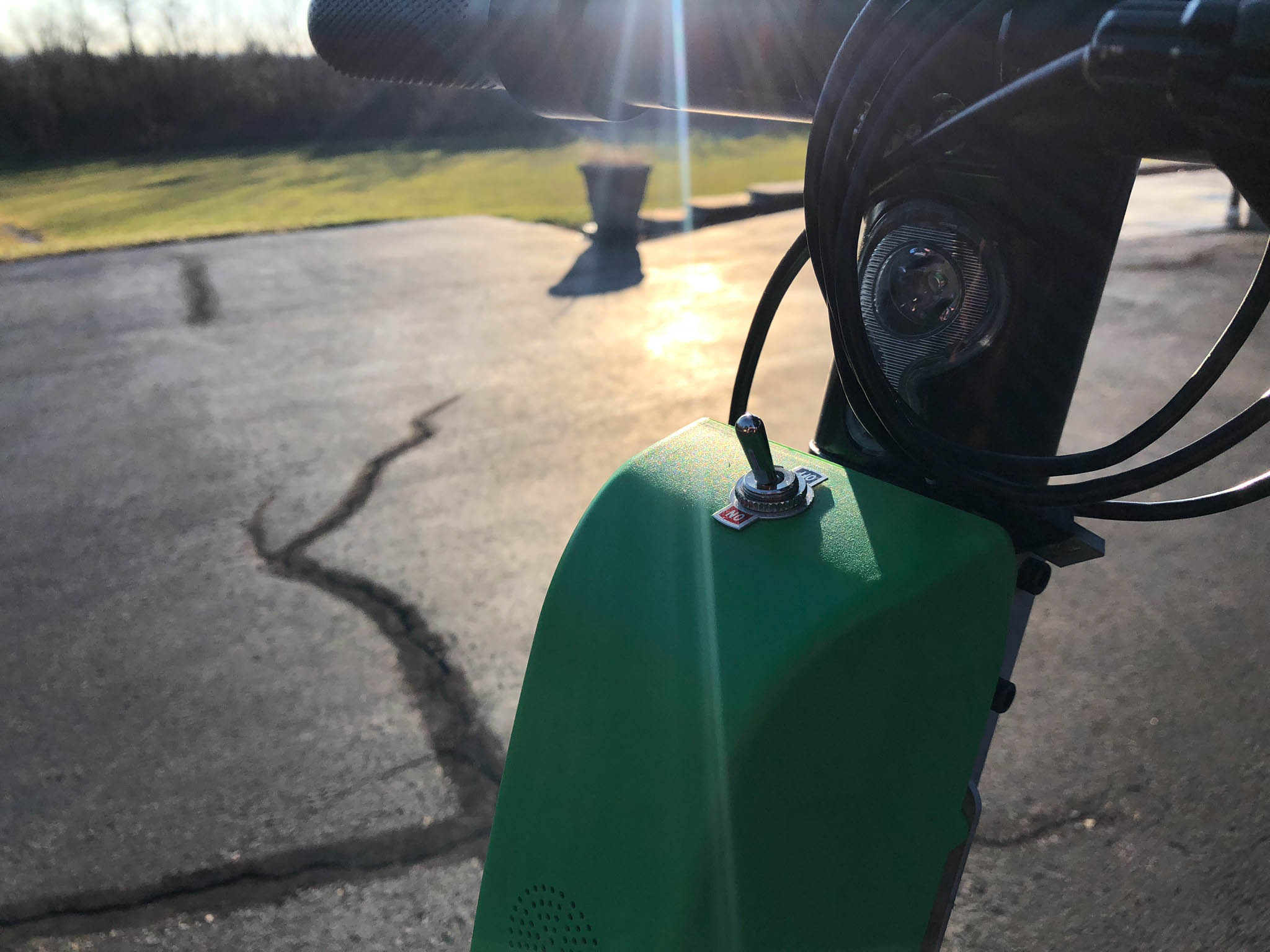
- The all-important switch
The ride isn’t perfect yet- the performance definitely feels a bit more sluggish than what I remember from riding scooters that were still in service while out in LA, but it certainly works well enough to ride around. The motor also sounds different when driven by our ESC. Oh well- we’ll continue to play with the tuning and see what happens. After all, that’s the real scientific method, right?
One last thing (AKA the boring part). I can’t stress enough that this scooter was already out of service and was obtained completely legally. Don’t try to just take one off of the street! They’re all equipped with GPS tracking.

