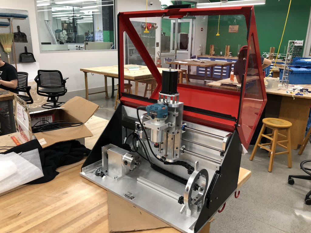
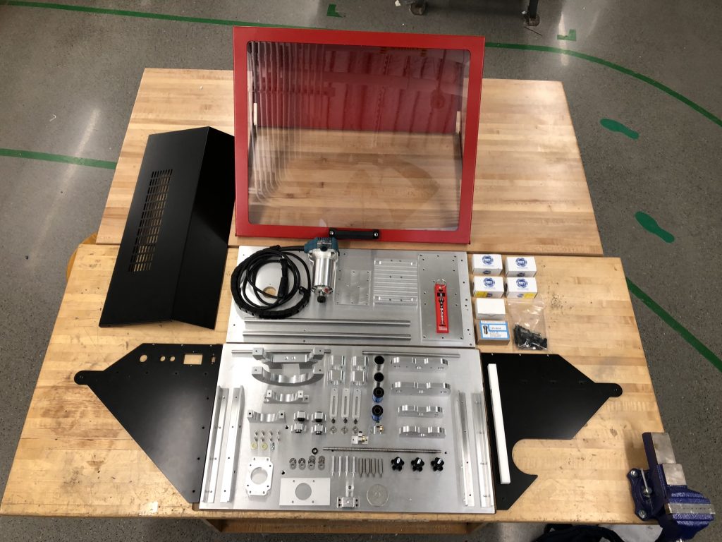
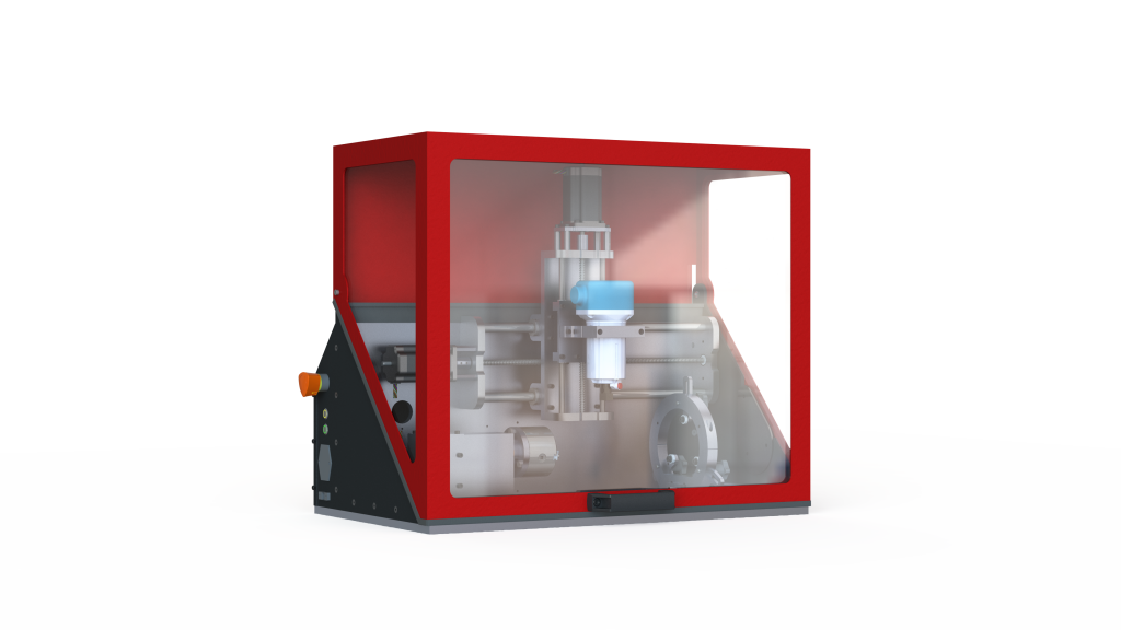
A three-axis rotary CNC built for the Mechanical Engineering senior design capstone course at Carnegie Mellon University by a team of engineering students. The CNC uses NEMA24 motors for each of the axes, with the X and Z axes actuated by lead screws,
and the A (rotary) axis actuated by a worm gear. The spindle is an off-the-shelf Makita hand router, which allows for any router bit
to be used.
Each motor is controlled by a stepper motor driver, which are all coordinated by an Arduino Uno running a customized version of the GRBL firmware. This is in turn controlled by a laptop running open-source GCode sending software.
To generate the GCode, we would create a 3D model of the part that we wanted to machine. We then “unwrapped” about the A axis. This basically takes the part and converts it from Cartesian coordinates to Cylindrical coordinates. 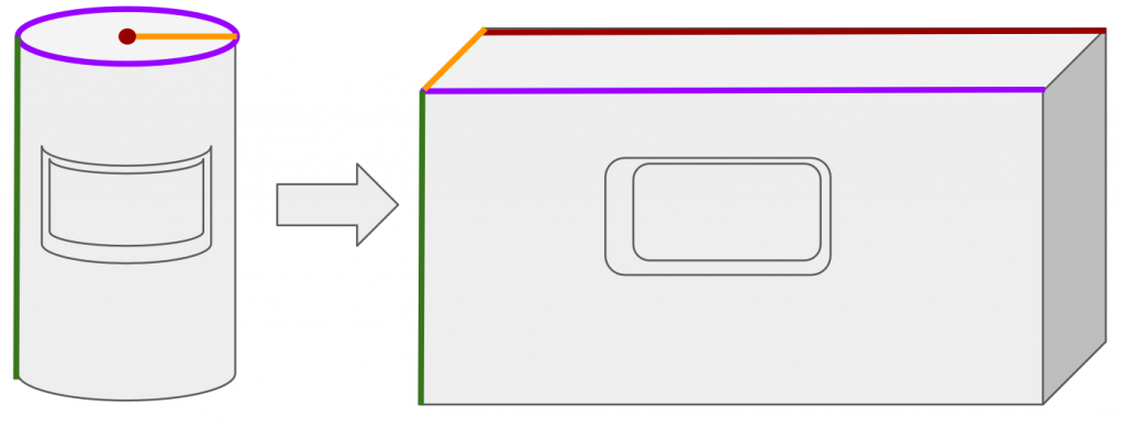 At this point, we could take the unwrapped part and load it into Autodesk HSM, a popular industrial CAM package. This allowed us to generate a toolpath for machining the part. We basically “fooled” the CNC into thinking that it was a normal, three-axis Cartesian CNC. The trick, however, is that the Y axis is wrapped around and becomes the A axis (see the image to the right to clarify this).
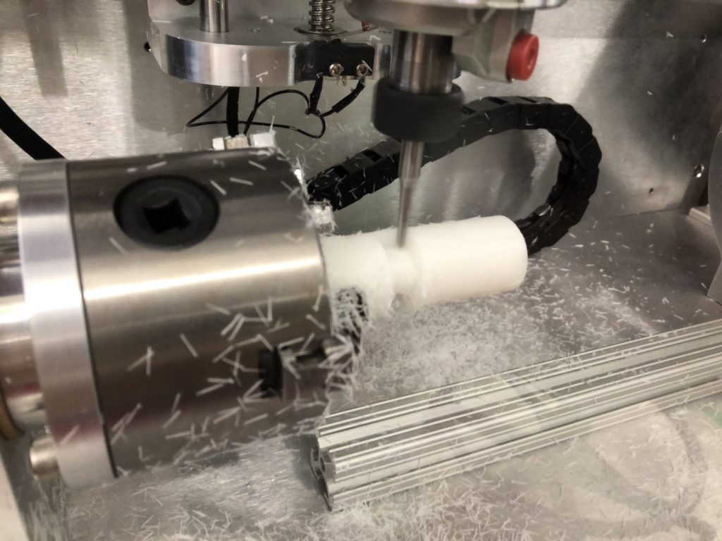
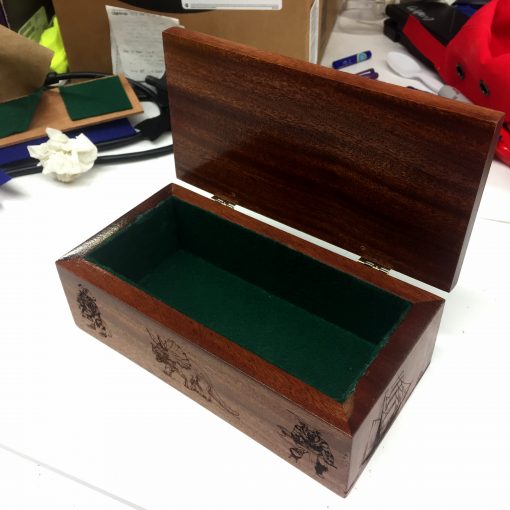
The CNC can easily cut softer materials such as plastic, wood, and foam. It was designed to be able to cut Aluminum as well, however we haven’t tested that feature yet. It’s on the list!


2 thoughts on “Three-Axis Rotary CNC”
cool
Found a post about this back on oct. 1st 2018, was wondering if this project has progressed any since it was written?
Not much like this is out there, even searching for a mill like this on Google is difficult/frustrating. The closest thing I could find like it was from a Russian company and was much bigger with a huge price tag to follow.
I would love to see something like this come to market, maybe just a bit bigger though, say 750-1k mm in length. I would also be interested in seeing the hardware and firmware set that was used, perhaps even a video of it running. The uses for a GRBL controlled rotary mill are plentiful, especially with 3D printing becoming much more reliable. I truly hope to see more come from this, well done!